Residential Decks
INFORMATION BULLETIN
211
April 2026
This Information Bulletin describes the minimum requirements for obtaining a building permit for an attached or detached deck accessory to a single-family dwelling or a duplex. The information bulletin cannot be used for decks located closer than 5 feet from a property line or when heavy concentrated loads such as equipment or a hot tub are placed on the deck. The information and sample drawings provided herein are suitable as a guide and cannot be used for construction. Project-specific construction plans must be drawn and provided for review. Decks containing unusual design features and framing irregularities must be designed by a registered design professional (licensed architect or civil engineer).
I. When Is a Permit Required?
A building permit is required for any residential deck that exceeds 200 square feet in area, when located more than 30 inches above grade at any point, when attached to a dwelling, or when it serves as the main exit door of the dwelling.
II. Submittal Requirements
- Forms
- Project Contacts Information Form (DS-345)
Owner-Builder Verification Form
This form is required if the property owner is acting as the general contractor. If you are not a licensed contractor and intend on performing the work yourself or hiring licensed subcontractors, an Owner-Builder Verification form (DS-3042) must be completed and submitted with your project documents.
Water Meter Data Card
A Water Meter Data Card (DS-16) must be completed if new plumbing fixtures are being added. This form is not required when replacing or relocating existing fixtures.
Plans
Plans must be drawn to scale and be of sufficient clarity to indicate the location, nature and extent of the proposed work. Existing and proposed construction should be clearly shown. Plans must show that all work conforms to the provisions of the current edition of the California Residential Code (CRC), the San Diego Municipal Code, and all other relevant laws, ordinances and regulations applicable in the City of San Diego.
Site plan and vicinity map (See Figure 1)
For detailed information, see Information Bulletin 122. For the required setback when the deck is located on a sloping site, see Figure 2.
- Plans for decks shall be in accordance to one of the following:
- Project-specific construction plans and framing system determined in accordance with this Information Bulletin. To facilitate plan review also mark on the bulletin the selected structural framing sizes such as decking, joists, beams, posts, foundation, etc.
- Engineered framed deck plans and design calculations. The plans should include a deck framing plan, foundation plan, elevations, cross sections, connection details, etc.
Overall plan
When the deck is proposed to be attached or located directly adjacent to an existing dwelling, include a floor plan of the deck and the existing dwelling and show the following information:
- The use and dimensions for all rooms in the building opening onto the deck.
- The location and size of all windows and doors opening onto the deck from those rooms.
- The location of the main exit door to the dwelling.
- Deck framing (See Figure 3)
- Framing members
- Decking and nailing (See Table F)
- Size of joists and beams (See Table A, B and C)
- Joist connection over beams (See Table F)
- Joist hung from ledgers (See Figure 8, Case 1)
- Size of posts based on the maximum heights (See Table D)
- Post footing and connection (See Table E, Figure 6)
- Lateral bracing
- Conventional diagonal bracing member and connection to beam and post, or decorative-diagonal bracings with an equal of the net area and (See Figure 4 and 10)
- Hold-downs at end of attached deck to existing dwelling (See Figure 11)
- Additional diagonal bracing for detached deck parallel to the exterior wall of existing dwelling (See Figure 8, Case 2)
Stair handrails
A handrail is required at least on one side of stairs with four or more risers. The required handrail shall be one of the following types:
- Handrails with a circular cross section shall have an outside diameter of at least 1.25 inches and not greater than 2 inches.
- If the handrail is not circular, it shall have a perimeter dimension of at least 4 inches and not greater than 6.25 inches with a maximum cross-section dimension of 2.25 inches. Edges shall have a minimum radius of 0.01 inch.
Guards
Guards shall be provided along the open side of a deck or stairs that are located more than 30 inches above the grade below. Guards shall be not less than 42” high, and openings in guards shall not allow passage of a sphere 4 inches in diameter. (see Figures 5, 9 and 10).
- Framing members
III. Additional Regulations
Smoke and Carbon Monoxide Alarms
When a deck is attached to a house or when the exterior wall of the dwelling is modified, smoke alarms and carbon monoxide alarms shall be installed within the dwelling as required per Section R310 and R311 of the California Residential Code (CRC).
- Very High Fire Hazard Severity Zone (VHFHSZ)
- Attached and detached decks when located in a VHFHSZ (map per an Diego Municipal Code (SDMC) Section 55.9401) , the material and method of construction used for the deck shall comply with State of California Wildland Urban Interface code (CWUIC).
Brush Management Zone
When a deck located within a Brush Management Zone, it shall comply with the City of San Diego’s Landscape Regulations, SDMC Section 142.0412.
Zoning and Planning Regulations
The following regulations typically apply to residential deck additions. Please consult the City of San Diego’s Land Development Code for all zoning regulations that may apply to your project.
Regulations | SDMC Section |
Residential Base Zones | |
Planned Districts | |
Brush Management | |
Landscape | |
Environmentally Sensitive Lands | |
Parking | |
Overlay Zones |
- Historical Review
Designated Historic
If the project involves any parcel containing designated historical resource, or is located within the boundaries of an adopted historic district, plans will be required and shall be submitted for Historical Review. Please refer to Information Bulletin 581, Designated Historical Resource Review for additional Historic Review information.
Potential Historic Resource
If the site contains buildings or structures 45 years old or older, and the scope includes any exterior work (except in-kind roof repair and replacement), plans and other information will be required and shall be submitted for Historical Review. For other potential historic review exemptions, see Municipal Code Section 143.0212.
IV. Options for Review Process
Plans for residential decks that require a building permit must be submitted electronically through the online portal, selecting Building Permit.
V. Project Fees
The following fees are required to be paid prior to review unless otherwise indicated below. For your convenience, DSD offers online payments. Payment may also be made in person by cash, check, debit card, Visa or MasterCard credit cards. Checks shall be in the exact amount, drawn on US banks, and made payable to the “City Treasurer.”
Refer to Information Bulletin 501, Fee Schedule, Construction Permits - Structures for all applicable fees.
Plan check fees and some administrative fees are non-refundable, but inspection fees may be refundable. For additional refund information, see the Refund Policy noted within Refund Application Form DS-721.
VI. Inspections
For inspection requirements, refer to Information Bulletin 120.
VII. Previous Versions
VIII. Figures
Figure 1-Sample Deck Site Plan
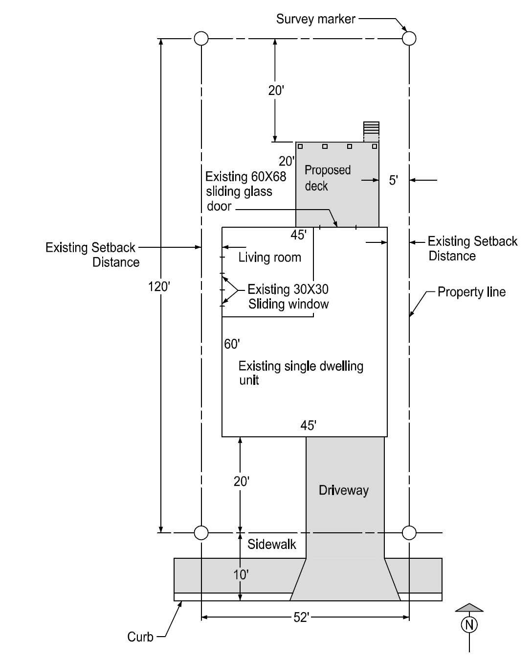
Figure 2-Structures on or Adjacent to Slope
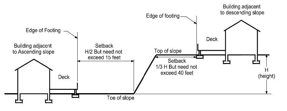
Figure 3-Typical Deck
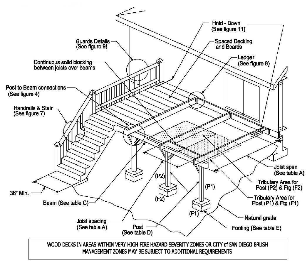
Figure 4-Post-to-Girder Connection
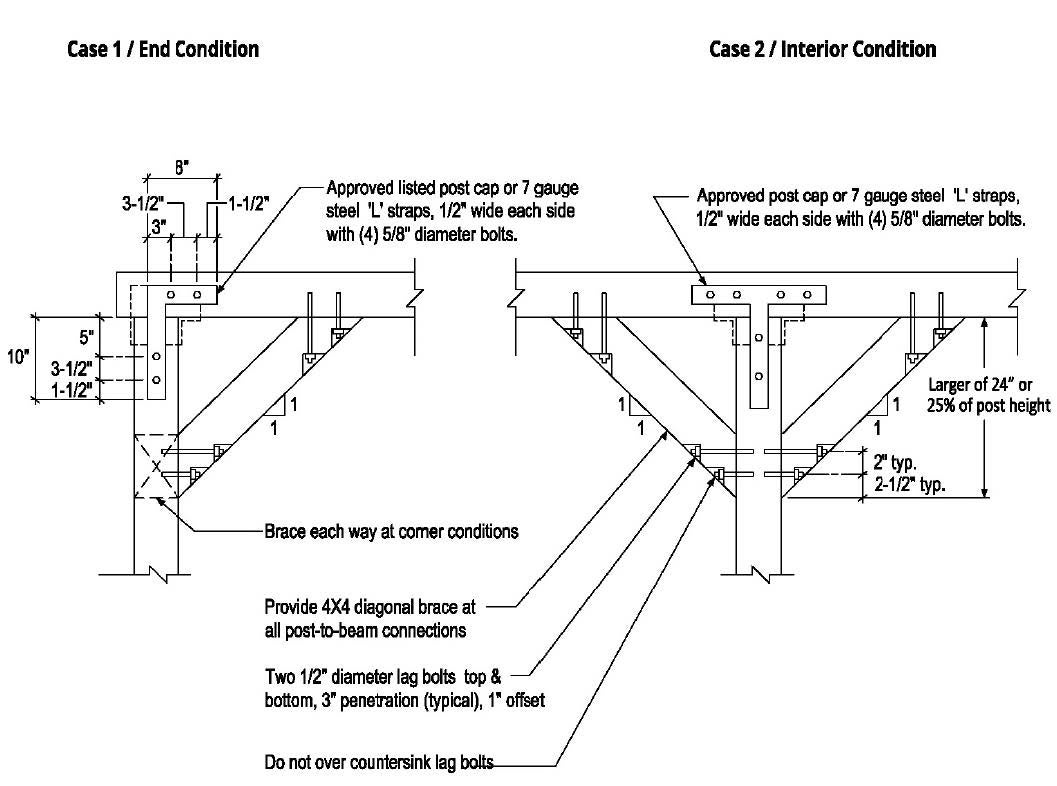
Figure 5-Typical Deck Elevation, Parallel to Rear of Dwelling
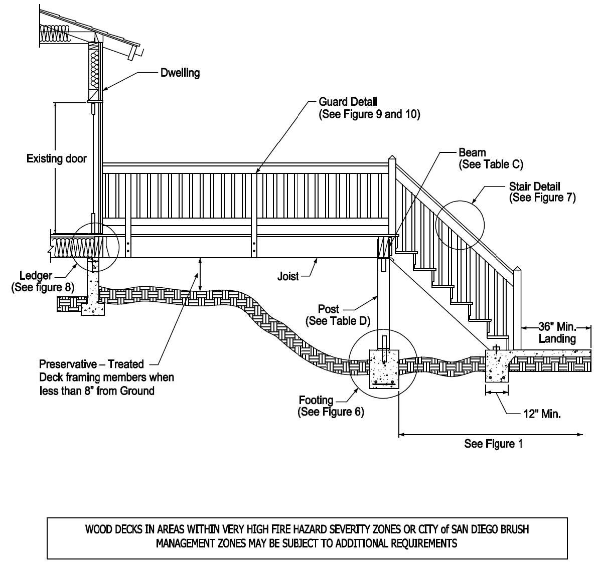
Figure 6-Typical Footing Detail
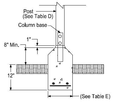
Figure 7-Typical Stair Detail
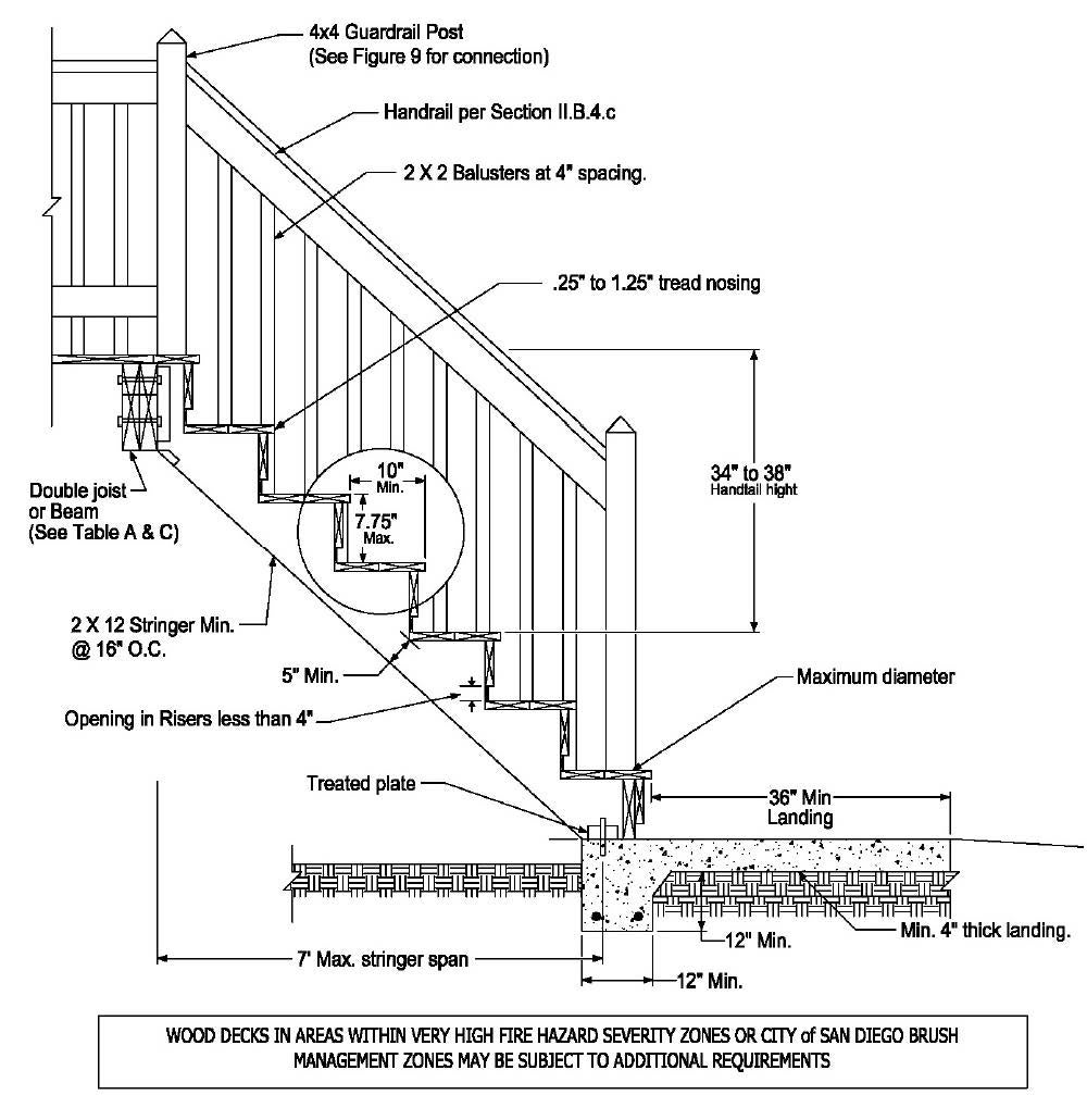
Figure 8-Typical Ledger Detail
Case 1-Leger to Rim Joist Connection (Attached Deck)
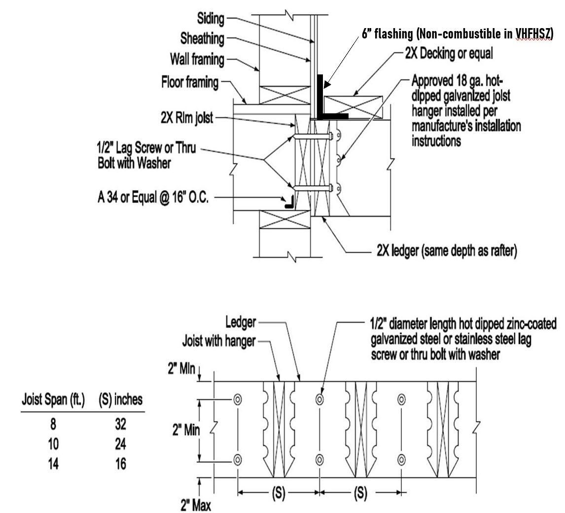
Case 2 –Rim Joist/Blocking at Stem Wall Connection (Detached Deck)
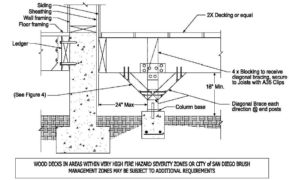
Figure 9 – Typical Guard Detail
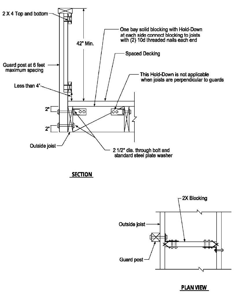
Figure 10 – Typical Deck Elevation
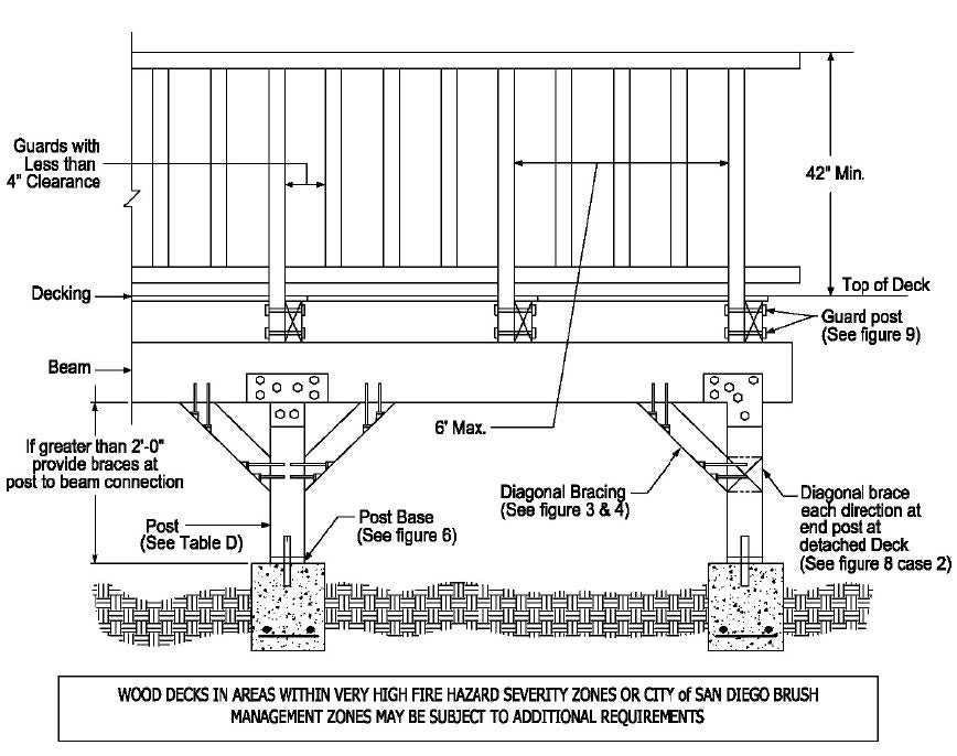
Figure 11 – Deck Attachment for Lateral Loads
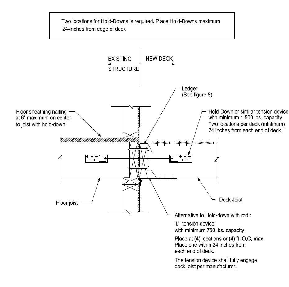
Table A - Allowable Span for Deck Joists (ft. - in.) 1,2,3
Species | Size | Spacing of Joists (inches) | ||
12 | 16 | 24 | ||
Douglas fir-Larch #2 or Redwood #1
| 2x6 | 6-9 | 6-2 | 5-1 |
2x8 | 8-10 | 7-10 | 6-6 | |
2x10 | 11-2 | 9-7 | 7-10 | |
2x12 | 12-9 | 11-2 | 9-1 | |
- Live Load= 60 psf, Dead load= 10 psf, L/△=360
- If joists within 8" inches of grade, use Pressure-Treated Douglas Fir-Larch or foundation-Grade Redwood.
- Include incising factor (Ci=0.8)
Table B - Cantilever Length for Deck Joists (ft. - in.) 1,2,5
Size | Spacing (inches)3,4 | ||
12 | 16 | 24 | |
2x6 | 1-0 | 0-10 | 0-9 |
2x8 | 1-7 | 1-6 | 1-5 |
2x10 | 2-5 | 2-2 | 2-0 |
2x12 | 3-2 | 2-10 | 2-3 |
- Live Load= 60 psf, Dead load= 10 psf, L/△=240
- The maximum cantilever length shall also be limited to one-fourth of the joist span.
- Joist spacing for diagonal decking shall not exceed 16 inches.
- Cantilever span includes 220 lbs. point load applied to end.
- Solid blocking shall be provided between joists over the support.
Table C-Deck Beams
Beam span lengths (ft.-in.)1,2,3,4,6,7
Species |
Size5 | Joist span less than or equal to:8 | ||||||
6 ft. | 8 ft. | 10 ft. | 12 ft. | 14 ft. | 16 ft. | 18 ft. | ||
Douglas Fir-Larch #2 Redwood #1 | 3 x 6 or 2- 2 x 6 | 3-9 | 3-3 | 3-0 | - | - | - | - |
3 x 8 or 2- 2 x 8 | 4-9 | 4-3 | 3-9 | 3-5 | 3-2 | - | - | |
3 x 10 or 2- 2 x 10 | 5-10 | 5-2 | 4-7 | 4-3 | 3-10 | 3-7 | 3-4 | |
3 x 12 or 2- 2 x 12 | 6-10 | 5-11 | 5-3 | 4-10 | 4-6 | 4-3 | 4-0 | |
4 x 6 | 4-6 | 3-10 | 3-5 | 3-3 | - | - | - | |
4 x 8 | 5-11 | 5-2 | 4-7 | 4-3 | 3-10 | 3-9 | 3-5 | |
4 x 10 | 7-0 | 6-2 | 5-4 | 4-10 | 4-6 | 4-3 | 3-10 | |
4 x 12 | 8-2 | 7-1 | 6-4 | 5-8 | 5-3 | 4-10 | 4-7 | |
3- 2 x 6 | 5-3 | 4-9 | 4-3 | 3-10 | 3-7 | 3-4 | 3-2 | |
3- 2 x 8 | 6-9 | 6-0 | 5-3 | 5-0 | 4-7 | 4-3 | 4-0 | |
3- 2 x 10 | 8-6 | 7-5 | 6-7 | 5-8 | 6-0 | 5-3 | 5-0 | |
3- 2 x 12 | 9-10 | 8-6 | 7-8 | 7-0 | 6-5 | 6-0 | 5-8 | |
- Live Load= 60 psf, Dead load= 10 psf, L/△=360 at main span.
- Beams supporting deck joists from one side only. See footnote (8) below for beams supporting cantilevered joists.
- Beam depth shall be greater than or equal to depth of joists with a flush beam condition.
- Beams within 8" of grade shall be Pressure-Treated Douglas Fir-Larch or Foundation-Grade Redwood.
- Beam piles shall be fastened with two rows of 10d threaded nails or #10d nails at 16"on center along the edges.
- Beams are permitted to cantilever not more than one-fourth of the span.
- Include incising factor (Ci=0.8).
- Beams supporting cantilevered joists:
To select a joist span from Table, use span length equal to joist span length + 125% of cantilevered length.
(Example: Joist with 12 ft. span & 3 ft. cantilevered length, calculated joist span = 12'+125% x (3')=15.75' therefore, beam allowable span shall be based on 16' joist span).
Table D-Deck Posts 1,2
Post Size | Maximum Height 3 |
4 x 4 | 4'-10" 4 |
4 x 6 | 7'-0" |
6 x 6 | 10'-0" |
8 x 8 | 14'-0" |
- Deck Loads: Live load= 60 psf, Dead load = 10 psf
- Species: Douglas Fir-Larch #1, or Redwood #1
- Measured to the underside of the beam.
- Maximum permitted height is 5'-8" when supporting one and two-ply beams.
Table E-Square Footing at Posts (Inches)1
Footing Dimensions | Tributary Area (sq. ft.) 5 | |||||||
20 | 40 | 60 | 80 | 100 | 120 | 140 | 160 | |
Width (in.) | 12 | 18 | 21 | 25 | 28 | 30 | 33 | 35 |
Depth (in.) | 8 | 8 | 10 | 10 | 12 | 12 | 14 | 16 |
- Footings shall have #4 @ 12" each way at bottom.
- Concrete strength minimum 2,500 PSI.
- Footing sizes are based on 1,500 PSF allowable soil bearing pressure.
- Footings shall be placed not less than 12 inches below the undisturbed ground surface.
- Area of deck surface supported by a post and a footing.
Table F-Nailing Schedule for Decks 1,3
Connection | Nails or Screws (Box or Common) |
Joist to Girder | 3-8d common nails |
2 inches nominal thickness spaced decking boards approximately 1/8" apart 2 | 2-8d threaded nails or 2 #8 screws |
- Decking within 8 inches of grade shall be Pressure-Preservative treated lumber or foundation-Grade redwood.
- Decking placement may range from an angle perpendicular to joists to an angle of 45 degrees to the joists. Each segment of decking must bear on minimum of 3 joists.
- All fasteners and connectors shall be hot-dipped galvanized or stainless steel.