Standard Cantilevered Retaining Walls
INFORMATION BULLETIN
221
December 2023
This information bulletin provides prescriptive reinforced masonry cantilevered retaining wall designs that are compliant with the San Diego Municipal Code and approved by the City of San Diego. This bulletin offers design alternatives for the construction of masonry retaining walls not exceeding 6 feet in height with level or sloping backfills. Sloping backfills shall have a maximum slope of 1.5 horizontal:1 vertical. Note that retaining walls 3 feet in height or less, measured from the top of the footing to the top of the wall, and less than 3 feet in height, meeting the conditions specified in Information Bulletin 220, do not require building permits.
I. Limitations
The retaining wall designs provided herein may not be used to retain expansive soils, surcharge loads, or to impound flammable liquids (for secondary containment). Furthermore, retaining walls provided in this bulletin may not be used in sites where the following geologic hazards exist:
- Fault Zones/Ground Ruptures
- Landslides/Potential Slope Stability
- Liquefaction/Potential Ground Failure
- Coastal Bluff Stability
- Variable Stability/Unfavorable Geologic Structure with Sloping Topography
Visit sandiego.gov/development-services/zoning-maps/seismic-safety-study to determine site-specific geologic hazards.
Retaining walls not conforming to the design criteria in this bulletin shall be designed by a civil engineer, structural engineer, or architect licensed in the State of California and are subject to special inspection requirements specified in Chapter 17 of the California Building Code. Retaining walls designed by licensed engineers or architects shall be submitted for plan review. The submittal package shall include plans and structural calculations. See Information Bulletin 220 for minimum plan content requirements. A geotechnical investigation may be required depending on the project location. All elements of retaining walls shall be maintained within the applicant’s property; encroachments into neighboring properties shall not be allowed.
II. Zoning Regulations
For zoning purposes, the height of a retaining wall is measured from the finished grade on the lower side of the retaining wall to the top of the retaining wall. Chapter 14, Article 2, Division 3 of the San Diego Municipal Code (SDMC) regulates the location and height of retaining walls in the required lot setbacks and in visibility areas as follows:
- Retaining walls in visibility areas shall not exceed 3 feet in height. (SDMC §142.0340(b)).
- Two retaining walls with a maximum height of 3 feet each are permitted in the required front and street side yard if the two retaining walls are separated by a minimum horizontal distance equal to the height of the upper wall. (SDMC §142.0340(c)(1)).
- Coastal Bluff Stability: Two retaining walls with a maximum height of 6 feet each are permitted in the required side and rear yard if the two retaining walls are separated by a minimum horizontal distance equal to the height of the upper wall. (SDMC §142.0340(d)(1)).
Zoning classification and additional requirements applicable to the project site will be determined during plan check. Applicant may schedule an appointment with DSD (Development Services Department) to determine zoning requirements prior to project submittal for plan check. Appointments for zoning services are available here.
Note: Retaining walls higher than 5 feet may require a grading permit.
III. Specifications
- Wall Height
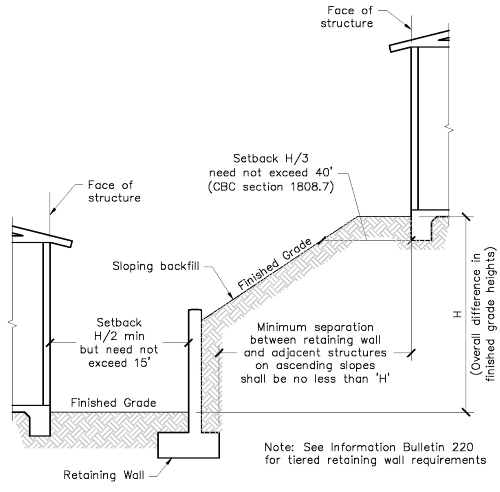
For structural design purposes, the wall height is measured from the top of the footing to the top of the wall (including wall caps). Wall configurations not covered in Tables A1, A2, or A3 of this document must be specifically designed for the actual proposed conditions by a registered design professional licensed in the State of California. Surcharge loads imposed by building foundations, driveways, parking areas, fences, etc., shall not be allowed on the wall’s upper level within a distance equal to the overall difference in finished grade heights, see Figure 4. - Concrete
Footings shall be constructed with normal-weight concrete; the concrete mix design used shall meet the following criteria:- Minimum compressive strength of 3,000 psi at 28 days (CBC, Table 1808.8.1).
- Type II Portland cement conforming to ASTM C150.
- ¾” aggregate conforming to ASTM C33.
- Water conforming to ASTM C1602.
- Water-to-cement ratio of 0.50
- Slump between 2- and 5-inches.
Masonry Blocks
CMU (concrete masonry units) shall be medium-weight units conforming to ASTM C90. CMU blocks shall have a minimum compressive strength of 2,000 psi and be laid in a running bond. CMU retaining wall assemblies shall be grouted solid.All head and bed joints shall be 3/8-inch thick. The bed joints of the starting course over the concrete foundation may be between 1/4 and 3/4 inches.
- Mortar
Type S or M mortar conforming to ASTM C270 shall be used in masonry construction. - Grout
Grout shall have a minimum compressive strength of 2,000 psi and conform to ASTM C476. - Reinforcing Steel
Reinforcing steel shall conform to ASTM A 615, Grade 60. ASMT A 615 Grade 40 may be used for #3 and #4 reinforcing bars only. Reinforcing shall be placed as specified in Figures 1a and 1b. Except for locations where control joints are installed per Figure 3, horizontal reinforcing shown in Figures 1a and 1b shall be continuous; as an alternative, lap splices specified in Figure 2 may be provided to meet this requirement. Vertical reinforcing shall be spliced as specified in the figures. All bars shall be clean of loose flaky rust, grease, or other materials likely to impair bond. - Mortar Key (optional)
A mortar key may be formed by embedding a flat 2x4 form flush with the top of the freshly placed footing to improve the bond between the footing and the first course of CMU blocks. The flat 2x4 form shall be removed after the concrete has started to harden. - Wall Drainage
Wall drainage shall be installed along the length of the wall, and it shall consist of a perforated drain pipe with a minimum diameter of 4 inches, protected with a filter fabric sock. The pipe shall discharge or connect to a stormwater collection system. Wall drainage discharging onto adjoining properties is prohibited. - Backfill
A 12-inch-wide layer of gravel shall be placed directly behind the retaining wall. This gravel layer shall extend from the top of the footing to a height that is 12 inches below the finished grade on the upper side of the wall. The balance of backfill shall be sandy or gravelly soil with Unified Soil Classifications of GW, GP, SW, or SP per Table 1610.1 of the California Building Code. - Guards
Guards shall be installed where the distance from the finished grade on the low side of the retaining wall and a walking surface on the high side of the retaining wall is greater than 30 inches. Guards shall be 42 inches high and have openings meeting the requirements of Section 1015.4 of the California Building Code. Only open railing guard configurations may be used in conjunction with the retaining wall designs specified in this document; guards with solid profiles are not acceptable. Retaining wall design accounts for guard load requirements specified in Section 1607.8.1 of the California Building Code. - Fences
Fences shall not be installed on top of the retaining wall designs specified in this document.
IV. City Inspections
City inspections must be performed during several phases of construction; see Information Bulletin 120 for information on how to prepare for and schedule inspections. Inspections shall be performed at the following times:
- A footing inspection shall be performed once footing excavation procedures are complete and the reinforcing steel is securely tied in its final position, but before concrete is poured.
- A pre-grout inspection shall be performed once the CMU blocks have been laid and the reinforcing steel is securely tied in its final position, but before the wall is grouted solid.
- If cleanout holes are used, CMU blocks may be laid to the full wall height before calling for the pre-grout inspection. Grout shall then be placed in a continuous pour.
- If cleanout holes are not used, a masonry pre-grout inspection is required prior to each grout pour. CMU blocks shall not be laid higher than the grout pour. Note that cleanouts are required for all grout pours over 5 feet in height.
- A backfill/drainage inspection shall be performed after grouting is completed and wall drains are in place, but before earth backfill is placed.
- A final inspection shall be performed once all work has been completed.
VI. Figures and Tables
Figure 1A: Typical Retaining Wall With Level Back Fill
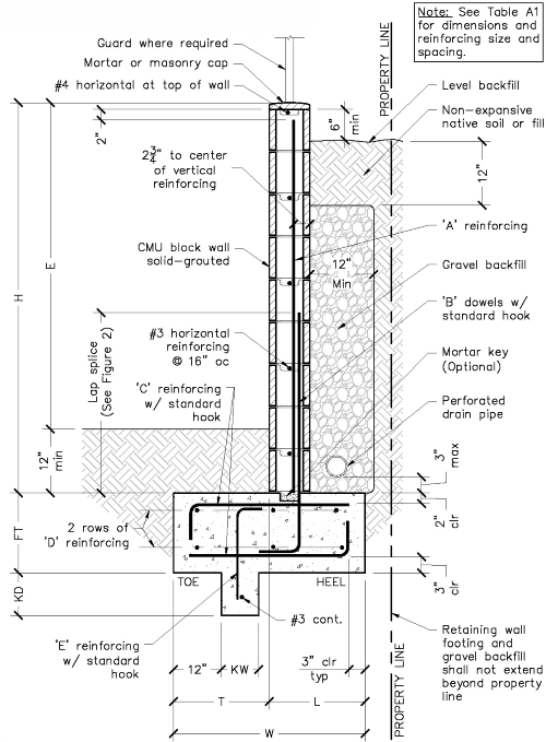
Table A1 / Requirements for Various Heights of Retaining Walls with Level Backfill
Wall Height (H) | 3'-4" | 4'-0" | 4'-8" | 5'-4" | 6'-0" |
Exposed Wall Height (E) | 2'-4" | 3'-0" | 3'-8" | 4'-4" | 5'-0" |
CMU Block Size | 6" | 8" | 8" | 8" | 8" |
Footing Width (W) | 1'-9" | 2'-0" | 2'-3" | 3'-0" | 3'-0" |
Heel Dimension (L) | 1'-3" | 1'-6" | 1'-6" | 2'-0" | 2'-0" |
Toe Dimension (T) | 6" | 6" | 9" | 1'-0" | 1'-0" |
Footing Thickness (FT) | 10" | 10" | 10" | 10" | 10" |
A Reinforcing | #3 @ 32" | #3 @ 32" | #3 @ 16" | #3 @ 24" | #3 @ 16" |
B Reinforcing | #3 @ 32" | #3 @ 32" | #3 @ 16" | #4 @ 24" | #4 @ 16" |
C Reinforcing | #5 @ 16" | #5 @ 16" | #5 @ 16" | #5 @ 16" | #5 @ 16" |
D Reinforcing | 2-#3 | 3-#3 | 3-#3 | 4-#3 | 4-#3 |
(Top & Bottom Total) | (4 total) | (6 total) | (6 total) | (8 total) | (8 total) |
E Reinforcing | - | - | - | - | #4 @ 16" |
Key Width (KW) | - | - | - | - | 6" |
Key Depth (KD) | - | - | - | - | 6" |
*See Figure 1a for retaining wall configuration. | |||||
Figure 1B: Typical Retaining Wall with Sloping Backfill
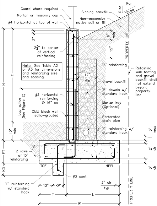
Table A2 / Requirements for Various Heights of Retaining Walls with Sloping Backfill
Slope = 2 Horizontal : 1 Vertical
Wall Height (H) | 3'-4" | 4'-0" | 4'-8" | 5'-4" | 6'-0" |
Exposed Wall Height (E) | 2'-4" | 3'-0" | 3'-8" | 4'-4" | 5'-0" |
CMU Block Size | 6" | 8" | 8" | 8" | 8" |
Footing Width (W) | 1'-9" | 2'-3" | 3'-3" | 3'-6" | 3'-6" |
Heel Dimension (L) | 1'-3" | 1'-6" | 2'-6" | 2'-6" | 2'-6" |
Toe Dimension (T) | 6" | 9" | 9" | 1'-0" | 1'-0" |
Footing Thickness (FT) | 10" | 10" | 10" | 10" | 10" |
A Reinforcing | #3 @ 24" | #3 @ 24" | #4 @ 24" | #4 @ 16" | #4 @ 16" |
B Reinforcing | #3 @ 24" | #3 @ 24" | #4 @ 24" | #4 @ 16" | #5 @ 16" |
C Reinforcing | #5 @ 16" | #5 @ 16" | #5 @ 16" | #5 @ 16" | #5 @ 16" |
D Reinforcing | 2-#3 | 3-#3 | 4-#3 | 4-#3 | 4-#3 |
(Top & Bottom Total) | (4 total) | (6 total) | (8 total) | (8 total) | (8 total) |
E Reinforcing | - | - | - | #5 @ 16" | #5 @ 16" |
Key Width (KW) | - | - | - | 6" | 6" |
Key Depth (KD) | - | - | - | 8" | 1-'0" |
*See Figure 1b for retaining wall configuration. | |||||
Table A3 / Requirements for Various Heights of Retaining Walls with Sloping Backfill
Slope = 1.5 Horizontal : 1 Vertical
| Wall Height (H) | 3'-4" | 4'-0" | 4'-8" | 5'-4" | 6'-0" |
Exposed Wall Height (E) | 2'-4" | 3'-0" | 3'-8" | 4'-4" | 5'-0" |
CMU Block Size | 8" | 8" | 8" | 8" | 8" |
Footing Width (W) | 2'-3" | 3'-0" | 3'-6" | 4'-3" | 4'-6" |
Heel Dimension (L) | 1'-9" | 2'-3" | 2'-6" | 3'-3" | 3'-6" |
Toe Dimension (T) | 6" | 9" | 1'-0" | 1'-0" | 1'-0" |
B Reinforcing | #3 @ 24" | #4 @ 24" | #4 @ 16" | #5 @ 16" | #5 @ 16" |
C Reinforcing | #5 @ 16" | #5 @ 16" | #5 @ 16" | #5 @ 16" | #5 @ 16" |
D Reinforcing | 3-#3 | 4-#3 | 4-#3 | 5-#3 | 5-#3 |
(Top & Bottom Total) | (6 total) | (8 total) | (8 total) | (10 total) | (10 total) |
E Reinforcing | #5 @ 16" | #5 @ 16" | #5 @ 16" | #5 @ 16" | #5 @ 16" |
Key Width (KW) | 6" | 6" | 8" | 8" | 10" |
Key Depth (KD) | 6" | 6" | 1-'0" | 1'-3" | 1'-8" |
*See Figure 1b for retaining wall configuration. | |||||
Figure 2 / Typical Reinforcing Hooks, Bends, and Splices
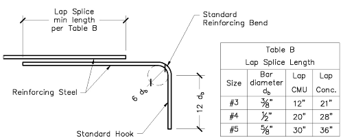
Figure 3 / Typical Control Joints

Figure 4 / Surcharge and Slope Setbacks